Image Geometric Correction
by Y. Ray Chuang
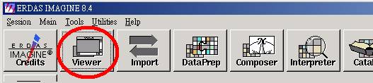
1. Open ERDAS Imagine 8.4.
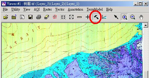
2. Open a map file with TIFF format (*.TIF) in Viewer # 1.
3. If RGB colors of map were reverse, click “Show Tool Palette”.
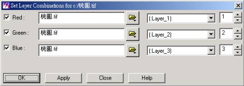
4. It will appear a Raster window, and then click “Change Band Combination”.
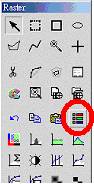
5. Change RGB layers from 3, 2, 1 to 1, 2,and 3. Then close the Raster window.
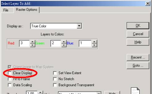
6. Click “Viewer” icon on main menu, and open the reference file.
7. If there were several reference files, cancel “Clear Display” in “Select Layer To Add”/“Raster Options” when adding next file. Now you can add all files in one viewer.
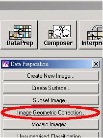
8. Click “Data Preparation” icon on main menu, and select “Image Geometric Correction”.
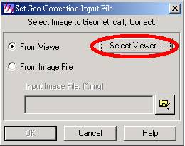
9. Choose “Select Viewer” in the Set Geo Correction Input File window.
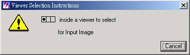
10. It will show an instructed window, and then click Viewer # 1.
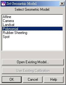
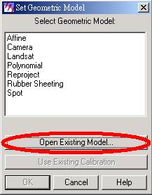
11. Select “Polynomial” model in the Set Geometric Model window.
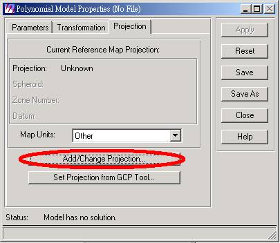
12. It will show two windows. One is “Geo Correction Tools” and the other is “Polynomial Model Properties”. Select “Add/Change Projection” in the Polynomial Model Properties window.
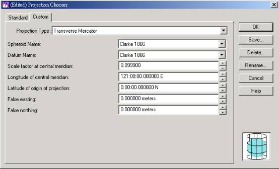
13. In the Projection Chooser window, select Transverse Mercator in Projection Type, and set Scale factor at central meridian to be 0.999900, Longitude of central meridian to be 121:00:00:00.000000 E.
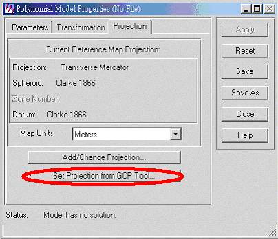
14. Then it will go back to Polynomial Model Properties window. Then select “Set Projection from GCP Tool”.
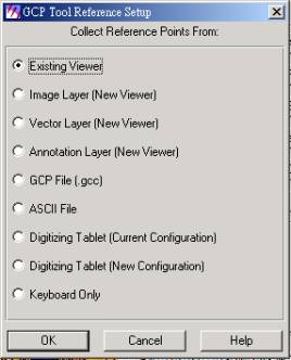
15. Choose “Existing Viewer”.
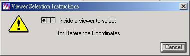
16. It will show an instructed window again, and then click Viewer # 2.
17. Click “OK” in the Reference Map Information window.

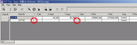
18. It will show the Viewer # 3 and Viewer # 4. They are zoom in viewers from white frames of the Viewer # 1 and Viewer # 2.
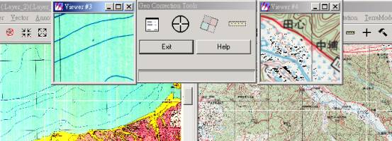
19. There is another GCP Tool window. Look for land features to correct from Viewer # 1 and Viewer #2. Click “Create GCP” to mark it in Viewer # 3.
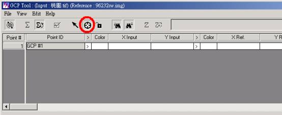
20. Then click “Create GCP” again to mark the same feature in Viewer # 4.
21. Before marking the next point, you should make sure the arrows are in the next data row.
22. You should better mark more than six points for correction and RMS should be less then 1.
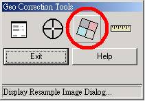
23. After marking six points, click “Display Resample Image Dialog” in the Geo Correction Tools window.
24. Name the output file and set the Output Cell Sizes.
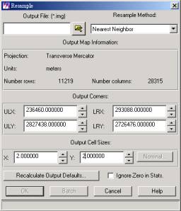
25. Click “OK” to start correcting.
26. After correcting, it will show a Verify Save on Close window when closing. If you want to correct another file, select save Geometric Model. Then you can select “open Existing Model” at step 6 when you correct another one.
27. Then save Input Points to the same folder with corrected file. Finally, it will ask you to save Reference Points and select “NO”.
28. Complete image geometric correction.